Configuring Links as Primary and Secondary with
auto fail-over.
In today’s world
having two or more links to the Internet is very essential, two Internet links
provide gateway redundancy. Moreover, it keeps up-time
optimum by having one link as a primary link and other
as the backup link.
Consider the below
network diagram:
NETWORK DIAGRAM
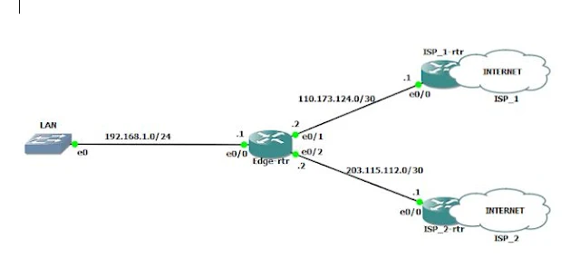
In above diagram
we have two DIA links from different ISPs (ISP-1 and ISP-2) and we want Internet link from ISP-1 to be primary and Link from ISP-2 to work as secondary or backup to ISP-1.
Configurations will be as follow:
On the edge router (i.e router
which is connected to ISP) you need do following 3-steps configurations:
*Note: All the configurations
are to be done on the edge router.
1) Interface Configuration
Step 1: Interface
Configuration
From the above network diagram
on the edge router
interface Ethernet0/1
interface Ethernet0/2
Step 2: IP-SLA, Track Object, and Default Route Configurations
IP-SLA
!
Track Object
!
Default Route Configurations
!
Step 3: Configuration for NAT Failover
!
interface Ethernet0/0
ip address 192.168.1.1
255.255.255.0
ip nat inside
full-duplex
!
!
access-list 1 permit
192.168.1.0 0.0.0.255
!
!
route-map NAT_ISP2 permit 10
match ip address 1
match interface Ethernet0/2
!
route-map NAT_ISP1 permit 10
match ip address 1
match interface Ethernet0/1
!
*Route-map is created to
match IP address define by access-list 1 and also match the exit interface.*
!
ip nat inside source route-map
NAT_ISP1 interface Ethernet0/1 overload
ip nat inside source route-map
NAT_ISP2 interface Ethernet0/2 overload
!
*These commands enable
Port Address Translation (PAT), where the IP addresses to be translated are
defined by the route-map. The IP address to be translated into are defined
after the interface keyword.*
To verify IP SLA and auto fail-over use below commands:
show track
show ip nat translations
Hope this was informative if have any doubt or suggestion feel free to comment
below
Configuring Links as Primary and Secondary with
auto fail-over.
In today’s world
having two or more links to the Internet is very essential, two Internet links
provide gateway redundancy. Moreover, it keeps up-time
optimum by having one link as a primary link and other
as the backup link.
Today we’ll discuss
and configure two such links as Primary and Secondary links with auto fail-over
capabilities.
Consider the below
network diagram:
NETWORK DIAGRAM

In above diagram
we have two DIA links from different ISPs (ISP-1 and ISP-2) and we want Internet link from ISP-1 to be primary and Link from ISP-2 to work as secondary or backup to ISP-1.
Configurations will be as follow:
On the edge router (i.e router
which is connected to ISP) you need do following 3-steps configurations:
*Note: All the configurations
are to be done on the edge router.
1) Interface Configuration
2) IP-SLA, Track Object and
Default Route Configurations
3)Configuration for NAT
Fail-over
Step 1: Interface
Configuration
From the above network diagram
on the edge router
interface Ethernet0/1
description PRIMARY LINK TO ISP-1
ip address 110.173.124.2 255.255.255.252
ip nat outside
full-duplex
!
interface Ethernet0/2
description BACKUP LINK TO ISP-2
ip address 203.115.112.2
255.255.255.252
ip nat outside
full-duplex
!
Step 2: IP-SLA, Track Object, and Default Route Configurations
IP-SLA
!
ip sla monitor 1
type echo protocol ipIcmpEcho
110.173.124.1 source-ipaddr 110.173.124.2
ip sla monitor schedule 1 life
forever start-time now
!
Track Object
!
track 1 rtr 1 reachability
!
Default Route Configurations
!
ip route 0.0.0.0 0.0.0.0
110.173.124.1 track 1
ip route 0.0.0.0 0.0.0.0
203.115.112.1 10
!
Step 3: Configuration for NAT Failover
!
interface Ethernet0/0
ip address 192.168.1.1
255.255.255.0
ip nat inside
full-duplex
!
!
access-list 1 permit
192.168.1.0 0.0.0.255
!
!
route-map NAT_ISP2 permit 10
match ip address 1
match interface Ethernet0/2
!
route-map NAT_ISP1 permit 10
match ip address 1
match interface Ethernet0/1
!
*Route-map is created to
match IP address define by access-list 1 and also match the exit interface.*
!
ip nat inside source route-map
NAT_ISP1 interface Ethernet0/1 overload
ip nat inside source route-map
NAT_ISP2 interface Ethernet0/2 overload
!
*These commands enable
Port Address Translation (PAT), where the IP addresses to be translated are
defined by the route-map. The IP address to be translated into are defined
after the interface keyword.*
To verify IP SLA and auto fail-over use below commands:
show track
show ip nat translations
Hope this was informative if have any doubt or suggestion feel free to comment below

No comments:
Post a Comment